If a LED (identified as ledPin in the Arduino sketch) does not shine after it is activated by
pinMode(ledPin, OUTPUT);
writeDigital(ledPin, HIGH)
check the LED is correctly wired:

LE ... Light Emitting
D ..... Diode
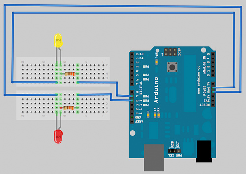
In diode, the electric current flows through the bulb in one direction, from plus/+ to minus/-. The LED has two wires. The long one, called anode, has a positive charge, the shorter wire, cathode, a negative one. We need to use resistors with LEDs. These components provide resistance to the electric current, therefore protecting the bulb. Resistence to the electricity flow is measured in ohms (Ω). As the current flows from + to - in a diode, the resistor must be positioned between Arduino and the LED's longer wire.
 http://www.digikey.com/~/media/Images/Marketing/Resources/Calculators/resistor-color-chart.jpg?la=en-GB
For the bottom example:
The cathode is connected to the Arduino GRD.
Calculating resistence of a resistor:
The last stripe on the right gives the tolerance (error range), the second from the right provides the amount of Ohm units, by which we need to multiple the number we assembled from the rest of the stripes, to give the resistance value. To find this number, we go from the left of the resistor and find the values corresponding to the rest of the stripes (all but the last two), which we just string together:For the bottom example:
- red ......... first band => digit 2
- orange ... second band => digit 3
- violet ..... third band => digit 7
- black ..... Ohm multiplier : 1Ω
- brown .... error tolerance : +- 1%
The cathode is connected to the Arduino GRD.
If a LED does not shine as strongly as it should, see if the corresponding line
is present in the sketch
An example of a sketch using two LEDs and a liquid crystal display (LCD 16x2) to show a stream of messages
#include <LiquidCrystal.h>

// initialize the library with the numbers of the interface pins
LiquidCrystal lcd(8,9,4,5,6,7);

unsigned char ledPin=1;
unsigned char ledPin2=2;

unsigned char j=0;

char *messages[4] = {
    "Hello child",
    "Hello husband",
    "Hello family",
    "Hello World",
};

void setup() {
    pinMode(ledPin, OUTPUT);
    pinMode(ledPin2, OUTPUT);

    digitalWrite(ledPin, LOW);
    digitalWrite(ledPin2, LOW);
    digitalWrite(ledPin, HIGH);

    lcd.begin(16,2);

    lcd.setCursor(0,0);
    lcd.print("*** Saying hello");

    lcd.setCursor(0,1);
    lcd.print("from Tamara");

    delay(2000);
}

void loop() {
    unsigned char i;

    if (j>1) { j=0; }

    if (j==1) {
        digitalWrite(ledPin, HIGH);
        digitalWrite(ledPin2, LOW);
    } else {
        digitalWrite(ledPin2, HIGH);
        digitalWrite(ledPin, LOW);
    }

    for (i=0;i<4;i++) {
        lcd.clear();
        lcd.begin(16,2);

        lcd.setCursor(0,0);
        lcd.print(messages[i]);

        lcd.setCursor(0,1);
        lcd.print("from Tamara");

        delay(1000);
    }

    lcd.clear();

    delay(1000);
    j++;
}
Connecting the LCD 16x2 to Arduino (without potentiometer)

www.fibidi.com
The result will be:
It is not be very clear in the video, but whenever each of the LEDs becomes lit up, the four messages:
    "Hello child",
    "Hello husband",
    "Hello family",
    "Hello World"
are displayed in succession, with a second of a pause in between. After the last message, the lights swap, and the messages are shown again, one after another.
No comments:
Post a Comment
Note: only a member of this blog may post a comment.