Search This Blog

Showing posts with label arduino. Show all posts

Tuesday, 2 December 2014

Controlling bubble machine with Arduino

Required parts

Arduino (UNO R3 used here)
Bubble machine
Relay board (I used one with two modules, but one module is enough)


LED
Resistor 1kΩ

Optional:
  • prototyping shield
  • mini breadboard
    or 
  • normal breadboard

These two parts are not required, one can use a normal breadboard, if preferred. The picture below not in proportion to the mini breadboard above.


Disassembling the Bubble machine

The Arduino sketch is dead simple. What I found trickier, was dealing with the hardware. Connecting everything together correctly, though, after I understood, how it all works, it is fairly simple too.
  1. Unscrew the back of the machine, to get to the wires. 
  2. The motor is connected to:
    1. the battery combo (negative change)
    2. the switch
  3. The battery combo is connected to:
    1. the motor
    2. the switch (positive charge)
  4. Disconnect both wires from the bubble machine switch

Hardware connections

Connecting the Bubble machine to the Relay module


The Bubble machine wires will be connected to the relay board on the left side, Arduino on the right.
On the left, there are 3 connections (from the top):
  • NO     ... Normally open (circuit)
  • COM  ... Power
  • NC     ... Normally closed (circuit)
If we connect positively/+ charged battery wire to NC and the Motor wire to the COM, the motor will start, because the circuit is closed by default.
We need to connect the battery wire to NO and the motor wire to COM.

Connecting the Relay module to Arduino


On the right side of the Relay board, there are several connections:
  • GRD ... Ground
  • VCC ... Power
  • IN1, IN2 etc ... Relay board output pins (each pin corresponds to one relay module)
The Relay GRD will be connected to the Arduino GRD, VCC needs to be connected to Arduino V5 pin and one of the Relay output pins will get attached to whichever Arduino digital pin we like. This pin will be used to control the Bubble machine.

NOTE


Please note that the setting:
 
      digitalWrite(controlPin, HIGH);

will NOT start the engine, because the default mode of the NO-COM connection is an open circuit. Rather counter-intuitively, we can start the engine with:

      digitalWrite(controlPin, LOW);

which closes the circuit by switching off the default, ie "not connected"/"open" setting to the non-default/"closed" one.

The Arduino Sketch

/* Control the bubble machine (powered by batteries) bubble machine is switched on at start, then off and on again a LED switches on when the machine is off and vice versa
   */ int controlPin = 7; void setup() { pinMode(controlPin, OUTPUT); digitalWrite(controlPin, LOW); // turn the bubbles on,
// the LED is off
} // the loop routine runs over and over again forever: void loop() { digitalWrite(controlPin, HIGH); // turn the LED on and bubbles off delay(6000); // wait for 6 seconds digitalWrite(controlPin, LOW); // turn the LED off and bubbles on delay(6000); // wait for 6 second }
 
The effect is that the Bubble machine, as soon as we power up the Arduino, will start and go on for 6 seconds. Then it will stop and the LED will light up for 6 seconds. Then the machine will be powered up again and the LED will be switched off for 6 seconds and so on and so on ...

Video of the inside of the bubble machine:


Bubbling away (with some extra LEDs for a bit more fun):


Saturday, 22 November 2014

Arduino LEDs related Tips & Tricks

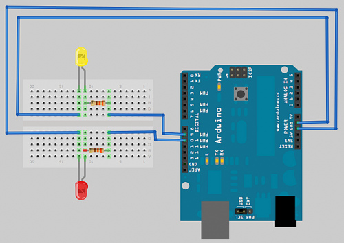
  •  If a LED (identified as ledPin in the Arduino sketch) does not shine after it is activated by

                     pinMode(ledPin, OUTPUT); 
                     writeDigital(ledPin, HIGH)              
                
                 check the LED is correctly wired:
                           LE ... Light Emitting
                           D ..... Diode

                  In diode, the electric current flows through the bulb in one direction, from plus/+ to minus/-.  The LED has two wires. The long one, called anode, has a positive charge, the shorter wire, cathode, a negative one. We need to use resistors with LEDs. These components provide resistance to the electric current, therefore protecting the bulb. Resistence to the electricity flow is measured in ohms (Ω). As the current flows from + to - in a diode, the resistor must be positioned between Arduino and the LED's longer wire.

 http://www.digikey.com/~/media/Images/Marketing/Resources/Calculators/resistor-color-chart.jpg?la=en-GB

Calculating resistence of a resistor:

The last stripe on the right gives the tolerance (error range), the second from the right provides the amount of Ohm units, by which we need to multiple the number we assembled from the rest of the stripes, to give the resistance value. To find this number, we go from the left of the resistor and find the values corresponding to the rest of the stripes (all but the last two), which we just string together:

For the bottom example:
  1. red ......... first band      => digit 2
  2. orange ... second band => digit 3
  3. violet ..... third band     => digit 7
  4. black ..... Ohm multiplier  :  1Ω
  5. brown .... error tolerance :  +- 1%
therefore 237 * 1Ω = 237 Ω, +-1%

The cathode is connected to the Arduino GRD.

  • If a LED does not shine as strongly as it should, see if the corresponding line

                      pinMode(ledPin, OUTPUT);       

                 is present in the sketch

  • An example of a sketch using two LEDs and a liquid crystal display (LCD 16x2) to show a stream of messages

#include <LiquidCrystal.h>

// initialize the library with the numbers of the interface pins
LiquidCrystal lcd(8,9,4,5,6,7);

unsigned char ledPin=1;
unsigned char ledPin2=2;

unsigned char j=0;

char *messages[4] = {
    "Hello child",  
    "Hello husband",  
    "Hello family",  
    "Hello World",  
};

void setup() {
    pinMode(ledPin, OUTPUT);
    pinMode(ledPin2, OUTPUT);

    digitalWrite(ledPin, LOW);
    digitalWrite(ledPin2, LOW);
    digitalWrite(ledPin, HIGH);

    lcd.begin(16,2);

    lcd.setCursor(0,0);
    lcd.print("*** Saying hello");

    lcd.setCursor(0,1);
    lcd.print("from Tamara");

    delay(2000);
}

void loop() {
    unsigned char i;

    if (j>1) { j=0; }
    
    if (j==1) {
        digitalWrite(ledPin, HIGH);
        digitalWrite(ledPin2, LOW);
    } else {
        digitalWrite(ledPin2, HIGH);
        digitalWrite(ledPin, LOW);
    }

    for (i=0;i<4;i++) {
        lcd.clear();
        lcd.begin(16,2);

        lcd.setCursor(0,0);
        lcd.print(messages[i]);

        lcd.setCursor(0,1);
        lcd.print("from Tamara");

        delay(1000);
    }

    lcd.clear();
    
    delay(1000);
    j++;
}

Connecting the LCD 16x2 to Arduino (without potentiometer)

www.fibidi.com


The result will be:


It is not be very clear in the video, but whenever each of the LEDs becomes lit up, the four messages:

    "Hello child",  
    "Hello husband",  
    "Hello family",  
    "Hello World"

are displayed in succession, with a second of a pause in between. After the last message, the lights swap, and the messages are shown again, one after another.